すべてのよくある質問
レーザーカンタム社の製品ポートフォリオ
The operating environmental temperature (air temperature) should be in the range of 16°C-26°C, the operating laser head temperature range is 20°C-24°C. The coolant temperature needs to be set to the final chiller setting given in the certificate of conformity (typically a value close to 22°C).
Related to: venteon/ taccor/ gecco
Please use an appropriate coolant preventing aluminum corrosion.
Recommended coolants are Glysantine G48 or LIQ-705CL-B (Koolance) in a 1:2 mixture with tap water. Set coolant temperature to the final chiller setting given in the certificate of conformity (typically a value close to 22°C).
Related to: venteon/ taccor/ gecco
If the laser is operated with a third party chiller, it must be ensured that the flow does not exceed 2 l/min and the pressure does not exceed 1 bar. Too high flow values can cause turbulent flow in the housing causing excessive noise on the output. Too high pressure can cause serious system damage.
Related to: venteon/ taccor/ gecco
There are different causes which can lead to a performance change of the laser system. Please check the following steps to ensure the performance change is not caused by an external factor. For gecco and venteon systems please ensure to check steps 1 – 7 prior to any cleaning or realignment. For venteon systems also include step 8 and 9.’
- 出力アパーチャーとパワー・メータの間に外部光学部品を使用せずに出力パワーを測定し、パワー・メータが正しい値に設定されていることを確認してください。
- システムの電源を完全に切り(電源ユニットを含む)、約30分待ってからシステムを再起動してください。
- 冷却システムが正しく動作していることを確認してください。
- チューブは接続されていますか?
- チラーはオンになっていますか?
- 液体は流れていますか?
- レーザー・ヘッドと電源ユニットの温度はどのくらいですか?温度は安定していますか?
- すべてのケーブルがレーザー・ヘッドと電源ユニットに正しく固定されていることを確認してください。
- ファイバーに損傷やよじれがないか確認してください。
- 循環液の振動がシステムの性能変化につながる可能性があるため、ファイバーがウォーター・ホースに接続されていないことを確認してください。
- Please ensure that the laser head is mounted on a flat and clean metallic surface with no more than a torque of 2Nm. If the base, where the laser head is mounted on, is slightly bent, if there is some debris between the laser head and the base or if the laser head is mounted with more than Nm, screwing down can lead to a bending of the laser housing, which affects performance. Please make sure that both sides (bottom face of the laser and the table) are clean. Unscrew the laser and check the output power again. The laser head can be screwed down gently while observing the output power. The power should not change by more than 2%.
- venteonレーザーの場合、分光計への適切な結合を確認してください。 くさび形の基板を使用してビームを選択する場合は、空間的な影響を避けるために、必ず前部反射を使用してください。 USB分光計は、Siベースの検出器感度に関して校正する必要があります。
- venteonシステムの場合、可能であれば、スペクトルを最適化するために電動分散ウェッジを動かしてください。
- geccoおよびventeonシステムの場合、前の手順で問題が解決しなかった場合は、マニュアルに従って光学部品を清掃してください。
- geccoおよびventeonシステムの場合、前の手順で問題が解決しなかった場合は、マニュアルに従ってキャビティを再調整してください。
- それでも問題が発生する場合は、サポートチームにお問い合わせください
There are different causes which can prevent the system from lasing or modelocking. Please check the following steps to ensure this is not caused by an external factor. For gecco systems please ensure to check steps 1 – 6 prior to any cleaning or realignment. For venteon systems also include step 7.
- システムの電源を完全に切り(電源ユニットを含む)、約30分待ってからシステムを再起動してください。
- Please ensure that the cooling system is running properly: a. Are the tubes connected? b. Is the chiller switched on? c. Is the fluid circulating? d. What are the temperatures of the laser head and power supply unit and are the temperatures settling?)
- すべてのケーブルがレーザー・ヘッドと電源ユニットに正しく固定されていることを確認してください。
- Please ensure that the key is turned to the 'on' position, the 'Laser' button is pressed and that the warm up phase is finished.
- ファイバーに損傷やよじれがないか確認してください。
- Please ensure that the laser head is mounted on a flat and clean metallic surface with no more than a torque of 2Nm. If the base, where the laser head is mounted on, is slightly bent, if there is some debris between the laser head and the base or if the laser head is mounted with more than 2Nm, the screwing down can lead to a bending of the laser housing, which affects performance. Please make sure that both the bottom face of the laser and the table are clean and screw it gently down while observing the output power. The power should not change by more than 2%.
- venteonシステムの場合は、電動分散ウェッジを反時計回り(-)方向に動かして、モードロックを開始してみてください。
- geccoおよびventeonシステムの場合、前の手順で問題が解決しなかった場合は、マニュアルに従って光学部品を清掃してください。
- geccoおよびventeonシステムの場合、前の手順で問題が解決しなかった場合は、マニュアルに従ってキャビティを再調整してください。
- それでも問題が発生する場合は、サポートチームにお問い合わせください
When the laser receives a back reflection from the setup (e.g. when coupling the laser output to a fibre) it is possible that the shutter closes automatically during operation. Therefore please avoid feeding back reflected light from optical components such as a fibre facet, which can be achieved by introducing a slight angle between the incoming beam and the component’s normal. Thus the reflected beam does not travel back the same way as the incoming beam. The coupling efficiency to a fibre should not be affected significantly by a small angle, FC/APC fibres are recommended.
If back-reflections into the laser can be excluded and the shutter still closes automatically, please contact us.
Related to: venteon/ taccor/ gecco
There are cases where the optics of a gecco or venteon need to be cleaned. This is only necessary if the gecco or venteon
- モードロックをセルフ・スタートしません
- 出力電力が低い
- 適合証明書に示されているスペクトルへの偏差を示します(例:スペクトルの狭まりまたは広がり、cwブレークスルー)
- Qスイッチを示しています
Cleanliness of the Ti:sapphire crystal, the mirrors and the windows within the gecco or venteon is of general importance for proper operation. For cleaning of the gecco or venteon optics please ensure to wear clean disposable gloves to avoid contamination. Remove the access panel, check for signs of contamination on the optics and disable the laser. Do not clean the optics whilst the pump laser is enabled! All optics within the gecco or venteon are cleaned with optics grade acetone and lens cleaning tissue.
Related to: gecco / venteon
Generally the gecco or venteon cavity should not be re-aligned. Only in the highly unlikely event that the performance changes described in FAQ 'When do the optics in a gecco or venteon need to be cleaned?' are not solved by repeatedly cleaning the optics or re-adjusting the pump power it is recommended to re-align the cavity.
For realignment, after referring to the user manual, please ensure to wear clean disposable gloves to avoid contamination and switch the gecco or venteon to maintenance mode via the user screen. Only use the two adjustable end mirrors of the cavity, M9 & M6 (OC) for the gecco and M8 & M6 (OC) for the venteon. Please read the user manual carefully prior to any realignment.
If the attempt to re-align the laser fails to bring the laser back in spec please contact our Support team.
Related to: gecco / venteon
Yes, each of our taccor, gecco and venteon systems can be purchased with the repetition rate control option. Control of the repetition rate and active feedback is enabled by cavity mirrors mounted on a fast and slow piezo crystal enabling rapid feedback and drift control simultaneously. In combination with the TL-1000 repetition rate stabilisation unit, timing jitter below 100fs can be achieved.
Alternatively, the repetition rate can be slightly changed by variations of the temperature of the cooling system. The change of the repetition rate is depending on the coefficient of thermal expansion of aluminium. Increasing the temperature leads to a smaller repetition rate, decreasing the temperature leads to a bigger repetition rate. In a taccor system for example, a temperature change of 1°C leads to a change in repetition rate of approx. 27kHz.
Related to: gecco / venteon / taccor
Yes, some care has to be taken so that the supported bandwidth of the steering mirrors is larger than the spectral width of the oscillator. Typically, coated silver mirrors should be used as standard dielectric mirrors may not be broadband enough.
Also, (dielectric) multistack mirrors may spoil the phase of the pulse, as they may introduce phase jumps in the spectral regions where the stacks join, which will destroy the compressibility of the pulse, i.e. the short pulse duration.
Related to: venteon
Measuring broad spectra as they are emitted by the venteon oscillator series requires an intensity calibrated spectrometer. The typical compact CCD spectrometer is not intensity calibrated, meaning that portions of spectrum are displayed differently from a measurement using a calibrated instrument. This is especially true for the long wavelength edge above 1000nm, which will be largely underestimated by non-calibrated spectrometers.
High accuracy intensity calibrated spectrometers include; the Ando AQ6317B, or the Yokogawa AQ6370.
Related to: venteon
The ultrashort pulses are made up of a coherent superposition of many different wavelengths, this is especially true for few-cycle pulses. When propagating through material, the wavelength dependent refractive index results in different propagation speeds for the different individual wavelengths (dispersion), which in turn results in a temporal broadening of the pulse (chirping of the pulse due to group velocity dispersion). To be able to measure the duration of few-cycle pulses, all dispersion in the beam path has to be compensated for, this is also true for the optics inside the measuring instrument. At these large bandwidths, the effect of the dispersion by propagating through a piece of 1mm fused silica is not negligible. As an example, the dispersion of the beam splitter of a typical autocorrelator has to be compensated for to be able to measure 5fs pulses.
Related to: gecco / venteon / taccor
For a near transform limited 5fs pulse as from the venteon ultra propagating through 10mm of BK7 glass, the pulse would be already stretched to 360fs. Propagation through 1mm of fused silica would stretch the same pulse to approx. 20fs, the same as travelling through 2m of air at room temperature. As an example, to compensate for passing through 15mm of fused silica (which adds about 540fs² of GVD) four bounces, off a pair of DCM11 mirrors, are needed (one pair of DCM11 mirrors introduces approx. -130fs² of GVD, i.e. approx. -65fs² per mirror)
Related to: gecco / venteon / taccor
For extremely short pulses, such as few-cycle pulses, this can best be done with a combination of Dispersion Compensating Mirrors (DCMs) and wedges. DCMs compensate the dispersion in discrete steps, and adding a pair of wedges enables continuous adjustment of the compensation to reach the optimal amount needed to gain the shortest pulse duration at the target. Alternatively, these can be combined together in a “pre-chirper” with motorized control to make regular alterations easier.
Related to: gecco / venteon / taccor
Ultrafast systems are used for applications that vary from customer to customer, so the final negative dispersion compensation needed for each set up, and possibly for each experiment, is different. It is Laser Quantum’s view that the negative compensation needed for the final interaction in the end users experiment is what matters and the compensation should be done only once, as this gives the user the best possible result.
Related to: gecco / venteon / taccor
To obtain the pulse duration measured during manufacture, the complete spectrum is needed. Also the outer low level wings do contribute considerably to getting the short pulse duration as specified. Thus, clipping the edges of the spectrum or using dispersive mirrors outside their specified range for the dispersive properties will result in degradation, and the pulse duration not being able to reach the value specified.
Related to: venteon
The venteon SPIDER is designed for input of an s-polarized beam, matching the s-polarized output from a venteon OPCPA. Other pulse diagnostic devices, such as e.g. autocorrelators, are typically designed for p-polarized input, matching the p-polarized output from the venteon as well as the taccor series of oscillators.
Related to: venteon/ taccor
There are different approaches to use; one would be to use a wave plate. However, the bandwidth of wave plates may be limited, and not rotate all wavelength components by the same amount. Also, the wave plate will introduce dispersion. A much more suitable option for use with extremely short and few-cycle pulses is the use of a polarization turning periscope, which is made from reflective optics suitable for handling the bandwidth whilst introducing only negligible dispersion.
Related to: gecco / venteon / taccor
The wedge inside the oscillator is not only used for coarse adjustment of the carrier envelope phase in CEP stabilized systems (the fine adjustment and stabilization is done via modulation of the pump power), but also for the fine tuning of the dispersion of the resonator. To obtain the extreme spectral bandwidth, in the range of a few hundred nm of the venteon series of oscillators, the overall dispersion of the resonator, while in mode-locked operation, has to be as close as possible to zero.
Therefore, the wedge position inside the resonator matters considerably for obtaining the broadest spectrum for the short pulse measured during production. Please keep in mind that the wedge position might be changed after installation since the ambient conditions are different from the place of production.
Related to: venteon
The venteon interferometers do not use small apertures in their setup, so beam pointing that would translate to a fluctuating power level of the CEP beat signal is not critical for the venteon CEP5 approach and does not need any stricter requirements compared to other techniques. Also, the signal power is not sensitive to temperature drifts or misalignment. In terms of stability, the CEP stabilized laser system (the pump laser and femtosecond oscillator) and f-to-2f interferometer are each built on an all-water-cooled monolithic breadboard, so thermal drifts are minimised as much as possible for those systems.
Related to: venteon
The venteon CEP5 approach does not require a PCF fibre for spectral broadening, the octave-spanning spectrum is obtained directly from the laser. There is no nonlinearity involved other than a simple SHG of the IR part of the spectrum in the f-to-2f interferometer!
Related to: venteon
Some applications require a spectrum with less bandwidth and smoother shape than offered by an octave spanning spectrum but still need CEP stabilization. To fulfil these requirements, the venteon power uses the more traditional approach - using a PCF fibre for spectral broadening, keeping a high power output from the oscillator with a smooth shape, less than octave spanning spectrum, for use in these experiments.
Related to: venteon
Not at all! The venteon f-to-2f interferometer is very compact, almost common path configuration and hands-off, so you don't have to touch it after installation. Should the beam in front of the interferometer be misaligned for some reason, there are three pinholes included in the setup and a readjustment can be performed by doing a beam-walk on these irises to obtain a good beat signal. This re-adjustment is very straight forward, since there are only two mirrors to align.
Related to: venteon
This approach still requires a nonlinear broadening, which can cause amplitude-to-phase noise conversion affecting the stabilization effort. Since the venteon spectra are broad enough, we don't need this technique and also require no fibres! (Except in the venteon power) The main advantage of the venteon CEP5 f-to-2f interferometer is that it needs only the wings of the spectrum as input and thus works with less than 20 mW of input average power, a really efficient approach! For the DFG approach > 15 0mW of power has to be used for the stabilization. Additionally, the venteon systems deliver much shorter pulses, so any CEP effect is much more pronounced!
Related to: venteon
The venteon CEP5 f-to-2f interferometer setup is almost common path. A common path interferometer is typically used with amplified pulses, where due to the available pulse energy a lower efficiency all-in-line setup can be used. With typical pulse energies from an oscillator however, the almost common path version is the most stable and efficient solution. Dividing and recombining the IR part only in the interferometer makes no major stability difference here as it is only a short path length built on a monolithic base. Choosing this way, makes the interferometer insensitive to dispersion of the in-line part of the setup, since the delay between both arms can be controlled easily. The frequency doubling and beat signal generation are all done in-line for best long term stability.
Related to: venteon
A SNR of >30 dB (@ 100 kHz detection bandwidth) for the beat signal is the standard specification of our systems, as well as typically that by other manufacturers. The venteon octave spanning oscillator typically delivers >40 dB SNR for the beat node from the interferometer (@ 100 kHz detection bandwidth) - venteon works in close collaboration with Menlo Systems for the CEP stabilisation and their locking electronic works very well with the power levels and SNR provided by the venteon interferometer.
Related to: venteon
ミラーは6°の入射角用に設計されていますが、0から10°の間はすべて問題ありません。15°を超えると、コーティングの特性がわずかにシフトし、振動の位相がずれます。
The standard pre-amp system is limited by the nonlinearities in the fiber amplifier, hence a 1nJ output energy. We can, however, customise a system that reduces the peak power by stretching the pulse prior to the input, followed, if required by post-amplification compression. In this way, we can boost the output of the 1µm narrow bandwidth beam up to ~100nJ at reduced repetition rate of 1 MHz.
Related: venteon
The power supply unit will automatically switch the laser off if the in-built over temperature protection system is activated. The laser can only be switched back on when the laser head has cooled down sufficiently.
In case of overheating please check that adequate heat sinking is provided to the laser head.
If a chiller is being used, please ensure that it is connected to the chiller plate on which the laser head is mounted and the fluid is circulating properly, this can be verified by opening the chiller and checking for movement of the water.
If the PSU has fans, please ensure that nothing is blocking them and check that all the fans are rotating properly.
If the cooling system and the fans are running properly and the laser head and /or the power supply unit are still overheating please contact our Support Team who will be happy to assist you.
For measuring the output power please use a calibrated power meter that is rated for use at the specified power of your laser. Ensure that the wavelength is set according to the value specified in the certificate of conformity and place the power meter in front of the output aperture. Please perform the measurement without any additional optics between the output aperture of the laser head and the power meter.
Related to: ventus/gem/torus/opus/finesse
There are different causes which can lead to a performance change of the laser system. Please check the following steps to ensure that the performance change is not caused by an external factor.
- 出力電力を正しく測定したことを確認してください(上記の項目5を参照)。
- システムの電源を完全に切り(電源ユニットを含む)、約30分待ってからシステムを再起動してください。
- 冷却システムが適切で適切に機能していることを確認してください(上記の項目3および4を参照)。
- すべてのケーブルがレーザー・ヘッドと電源ユニットに正しく固定されていることを確認してください。
- Please ensure that the laser head is mounted on a flat and clean metallic surface with no more than a torque of 2Nm. If the base, where the laser head is mounted on, is slightly bent or if there is some debris between the laser head and the base or if the laser head is mounted with uneven torque on screws leading to a bending of the laser housing, this could affect performance.
- レーザー開口部に向け直されるレーザー光の後方反射がないことを確認してください。
- If a fibre delivery system is present; Please check if there is any damage or kinks visible on the fibre. Please ensure that the fibre is not tied to any water hoses as the vibrations of the circulating fluid can lead to a performance change of the system.
- すべてのチェックを完了しても問題が解決しない場合はレーザーカンタムのサポート・チームにご連絡ください。喜んでサポートさせていただきます。
There are different causes which can prevent the system from lasing. Please check the following steps to ensure that this is not caused by an external factor.
- システムの電源を完全に切り(電源ユニットを含む)、約30分待ってからシステムを再起動してください。
- 冷却システムが正しく動作していることを確認してください。
- チューブは接続されていますか?
- チラーはオンになっていますか?
- 液体は循環していますか?
- レーザー・ヘッドと電源ユニットの温度はどのくらいですか?温度は落ち着きますか?)
- すべてのケーブルがレーザー・ヘッドと電源ユニットに正しく固定されていることを確認してください。
- Please ensure that the key is turned to the 'on' position, enabled and that the warm up phase is finished.
- Check and ensure that the pump diode drive current is set to a value above lasing threshold, e.g. use a value in the between 50% - 100%
- それでも問題が発生する場合は、レーザーカンタムのサポート・チームにお問い合わせください。
Using measurements the thermal resistance of the forced air cooling plate was calculated to be 0.08C/W. This means at normal laboratory temperatures and conditions, the temperature of the 6W opus 532 can be maintained
Related: opus
はい、finessやopusなどのグリーン・ポンプ・ソースは、psモードまたはcwレーザーで動作するTi:Sレーザーの励起にも適しています。 既存の顧客は、これらの分野でレーザーカンタムのレーザーをうまく適用しています。
ケンブリッジ・テクノロジーの製品ポートフォリオ
For a complete list of FAQ's on our ScanMaster Controller, click here
あなたは私たちのガイドでより多くの情報をここで見つけることができます
データ・ケーブルのステータス・チャネルに導通があることを確認してください。 結果にパリティー・エラーがないか確認してください。 パリティー・エラーがある場合は、コントローラが誤ったパリティーを予期しているか、接続が切断されていることを示しています。 XY2 100プロトコルの詳細の章で説明されているように、ステータス信号のフォーマットを確認してください。 これらの解決策のいずれも問題を修正しない場合は、テクニカル・サポートに連絡してください。
まず、ミラーに障害物がないことを確認します。 ミラーが移動できることを確認したら、適切な電源接続が行われていること、および電源が供給されていることを確認します。 次に、モーターへの接続を含め、他のすべての接続が正しく行われていることを確認します。 それでもシステムの電源が入らない場合は、テクニカル・サポートにお問い合わせください。
システムがオンになっていて、制御デバイスが適切な信号を送信していることを確認してください。 コマンド・ケーブルの導通を確認し、コントローラーへの接続がしっかりしていることを確認してください。 それでもシステムがコマンドに反応しない場合は、テクニカル・サポートに連絡してください。
In certain demanding applications, a significant amount of power is consumed in the motor that generates significant heat in the motor coil. This heat can propagate through the motor body and rotor, change the motor parameters as well as the encoder response, and compromise the system's accuracy. To address this potential problem, we have developed active cooling solutions to regulate the motor's temperature.
状態空間モデル、スキャナー・システムの正確な表現のおかげでLightningTM IIは広範囲の負荷を駆動できます。 このアルゴリズムは、最大4つの共振周波数をモデル化できるため、利用可能なサーボ電子機器では駆動できない負荷を制御できます。 カスタム・ロードを使用してシステムを構成するには、テクニカル・サポートにお問い合わせください。
Lightning II systems incorporate six* differentiating elements:
- Encoder Position Detector - Advanced encoder technology and state-of-the-art galvo motor design provide ultra-high resolution and ultra-low drift, resulting in unsurpassed
- PWM Drive Output - Extremely efficient power transfer from the driver to the motor enables unmatched speed and accuracy even with very large
- Observer-based State-space Modeling - The control algorithms in the servo driver are tailored to a specific motor / mirror combination, which enables the servo to achieve maximum performance in speed and
- GSB Communication Protocol - The General Scanning Bus, a new bi-directional high speed serial communication protocol between controller and servo driver(s), delivers sophisticated control to the scanners, and status and streaming probe data to the
- ScanMaster Control Software - Utilizing a single USB connection between a computer and the scanning system, this revolutionary control software provides automation and optimization far better than any other
- TuneMaster II Setup Software - Automated and user-friendly tools help shorten optimized tune development, automate production tuning and improve
The LED on the LightningTM II digital servo driver is currently* used as a general diagnostic indicator. During normal operation the LED remains constantly illuminated when the driver is idle, and flickers when the servo is issuing commands.
If the LED is not illuminated at all, this indicates a problem, and you may experience problems with communication. Verify the power to the board is connected correctly (connector pins and voltage levels). If the power connection is correct, contact Cambridge Technology for technical support.
* Future versions of the firmware might re-define this LED function
これは、ミラーの慣性、角度、およびコマンド波形によって異なります。
LightningTM IIは、従来のフィードバック・アーキテクチャではなく、オブザーバー・ベースの状態空間モデリングに基づいており、調整プロセスは従来のPID調整とは異なります。 Lightning IIシステムを受け取ると、工場で調整され、アプリケーションの要件に合わせて最適化されています。 ただし、高度なモデリングにより、パフォーマンスを損なうことなく、最適化されたチューンをさまざまなアプリケーションで使用できることがわかります。
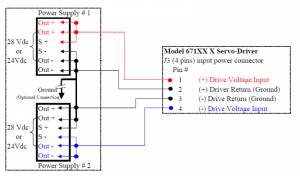
Depending upon how the supply is configured or the distance between the supplies and the driver boards, the S + may have to be connected to the Out + either right at the supply or at the driver board and the S - may have to be connected directly to the Out - either right at the supply or at the driver board.
The ground connection between the Out - and Out + and the ground connection between the two servo drivers should be a very heavy gauge low resistance wire.
The power supply ground connection is optional and is usually not connected.
For a complete list of FAQ's on our CRS series, click here
単一のCRSセットの場合は、12Vおよび1Aの電源をお勧めします。CRSは1つの周波数でのみ動作し、非常に効率的で、多くの電力を必要としません。
Synrad製品ブランド
どのくらいの数のノヴァンタによって設計された
CO2レーザーが使用されていますか?
現在、世界中で、250,000を超える当社のSynrad製品ブランドのCO2レーザーが稼働しています。 メーカーが弊社レーザの能力および利点に精通するにつれて、その数は急速に増加しています。
The exact components necessary to operate a laser depend on your application. All applications require some kind of “beam delivery system” or means of directing the laser beam to the work surface, and changing or focusing the beam. Turning mirrors and focusing lenses may be used to accomplish this.
You will also need some sort of motion system, such as an XY table, galvo scanning head, or plotter mechanism, an AC/DC power supply, and depending on the power of the laser you are using, a cooling system for the laser.
いいえ。 逆に、弊社の密封CO2レーザーは、操作が非常に簡単で、特別な訓練を必要としません。 レーザをセットアップするだけで、後の仕事はレーザ自体が行います。 それほど簡単なのです。 メンテナンスは不要です。
Lasers are actually safer than most types of machinery. Precautions are very much dependent on your application. The primary danger of lasers comes from the possibility
of the laser beam being reflected from the work surface. An acrylic or polycarbonate screen usually offers sufficient protection. Safety glasses or goggles should always be worn when the laser is in operation.
レーザー・ヘッドの大きさは、モデルによって異なります。Synradレーザーは、最小で17インチです。
他のレーザー技術は定期的なメンテナンスおよび/またはレーザー使用のための流動ガスのような使い捨てを必要としますが、Synradの密封CO2レーザーは、動作するためにメンテナンスや追加の使い捨てを必要としません。 Synradは、単純な設計、DCパワー・インおよびレーザー・パワー・アウトを採用しています。 当社の特許取得済みの「オール・メタル・チューブ」テクノロジーは、実質的にメンテナンス・フリーです。 Synradレーザーは、ガスの補充が必要になるまでに数千時間動作すると予想されます。
SynradのCO2レーザは、アクリル、発泡体、セラミック、ガスケット、木材、紙、プラスチック、テキスタイル、ゴム、ステンレス鋼、チタン、薄い金属、および他の多くを含む広範囲の材料に対してマーキング、刻印、ドリル加工、溶接、切断、穿孔を行うことができます。 詳しくは用途をご覧ください。