Understanding Pulse Width Modulated CO2 Laser Operation
Authors: Justin Conroy & Malte Hemmerich
要約
Common industrial CO2 lasers, both pulsed and continuous wave (CW) types, are controlled via Pulse Width Modulation (PWM) signals. While these input signals are simple square waves, the actual optical output of the laser is also affected by several physical laser characteristics, and it is therefore more complex. For these reasons, understanding the differences between the input PWM signal and the resulting optical output signal of the laser is key to choosing the right laser type and to optimize the laser operation process. In this whitepaper, we compare and explain the emission dynamics at various duty cycle / frequency settings for typical RF driven CO2 lasers using a Synrad (a Novanta brand) ti100 continuous wave laser and a Synrad p100 pulsed laser as examples.
PWM Signal Definition and Its Effect On RF Driven CO2 レーザー
Radiofrequency (RF) driven, all metal tube CO2 lasers provide big advantages over direct current (DC) driven, glass-tube CO2 lasers with respect to lifetime, beam quality and power stability. Unlike DC drivers, RF drivers cannot be operated at a fraction of their designed output power. Instead, RF drivers can be activated and deactivated within the kHz range which provides the required method to control the laser output quickly and accurately.
Subsequently the control signal for a RF driven CO2 laser is a Transistor–Transistor Logic (TTL) square wave with 0 V as the low state and 5 V as the high state. Note that equally to the RF stage functionality, there is no amplitude modulation in between these two voltages in the input signal. Therefore, a frequency and a duty cycle, the on-to-off ratio in percentage, are all required parameters to fully describe a PWM signal (see Fig. 1). During the low state of the PWM, the RF energy source of the laser tube is off, while during the high state the RF is pumping electrical energy into the laser cavity.
The actual emission of the laser beam is not instantaneous upon receipt of the PWM high signal as there will be a couple microseconds delay for the RF electronics to process and then another 50 – 100 µsec for the laser to reach full power or go down to zero emission.
When using a rather high frequency, the duty cycle of the signal will accurately control the laser output power of the laser. This control method is required as setting the average laser output power is crucial for ensuring enough energy is being delivered to achieve the process quality and speed desired but not over-burn the material with too much optical energy.
Fig. 1. Example of PWM Input Signal
For the most part, the percent duty cycle will linearly match the percent of possible output power in wattage from the laser tube. However, at very low duty cycles with short pulse periods, the RF would not supply enough energy to the tube to ensure a constant plasma breakdown in the tube which is a prerequisite to active laser emission. To prevent this from happening, most lasers use an additional, usually internal, “tickle”-signal that ensures a constant plasma breakdown while not adding so much energy that actual laser operation would occur. At very high duty cycles the efficiency of the laser tube will typically decline. Therefore, calibrated correction curves can be used in the external laser controller to achieve a linear duty cycle to optical power relationship. As plasma breakdown efficiency and other physical parameters differ from laser to laser and slightly change over time, these correction curves are individual to each unique laser and should be looked at from time to time.
The other critical parameter to be looked at is the period/frequency of the PWM signal and its relationship to the optical rise-and-fall time of the laser. At a basic level the command frequency is directly related to the on/off frequency of the RF stage and therefore the maximum acceptable input frequency, like its maximum duty cycle, is defined by the incorporated RF architecture. At this point it is important to understand that the given frequency range on its own is neither good or bad, nor can it describe the laser performance in any way. Only when looked at in combination with their acceptable duty cycle and the rise-and-fall time of the laser cavity, can one make assumptions of that laser’s performance at various parameter settings.
For low frequencies with periods which are significantly longer than the rise-and-fall-time of the laser, there will be distinct optical pulses which go from the ground state to the maximum possible peak power. Then, as the commanded period is shortened and approaches the rise-and-fall-time of the laser, the optical pulses will start to merge, and the peaks and valleys start to flatten out. At really short periods relative to the rise-and-fall-time, the pulses become barely distinguishable, and the optical output approaches a continuous wave behavior.
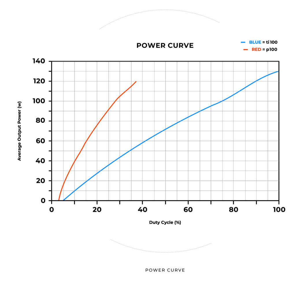
Fig. 2. Example of PWM vs. Wattage Graph for ti100 (CW) and p100 (Pulsed) Lasers
To summarize, the input PWM frequency is ultimately determining how the laser energy is distributed over time while the duty cycle will decide on the average power output. However, whether a Laser will operate in CW-mode or pulsed mode at certain PWM settings and which mode is needed for a specific application process, is a different story that needs to be told.
Continuous Wave Laser Operation
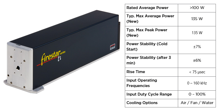
To design an industrial laser for continuous wave (CW) operation, it is crucial to optimize the RF, the electrodes and the gas-mixture towards high power stability, low wavelength drift and high duty-cycle ranges. A typical laser in this category is Synrad’s Firestar ti100 Laser, that can be run with a maximum PWM signal of 99-100% duty cycle at frequencies up to 160kHz (see Fig. 3).
Due to the design choices mentioned above, with a CW laser it is easy to find an operating range that will produce flat optical output. Even in cases of low duty cycle operation, there is minimal depth of power modulation or beam/wavelength instabilities. Examples of where this is needed are common vector marking and coding applications of human readable text, precision cutting applications where very smooth edges are needed such as thick acrylic cutting or thin plastic labels, and heat-treating applications.
However, while such a Laser can be given lower duty cycles and frequencies that will allow to get distinct optical pulses, the peak power of those pulses will only be as high as the average power rating of that laser. Thus, the energy per pulse isn’t very high compared to a “pulsed” laser which is discussed in the next section. Its strength is lasing for long continuous periods of time and relatively stable CW emission even at reduced power levels.
Fig 3. Popular CW Laser Model from the Synrad Product Line, ti100
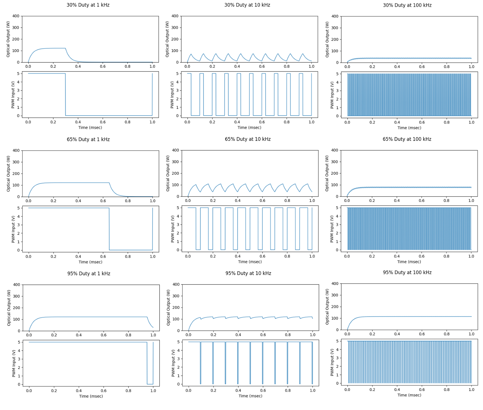
Figure 4 shows the output characteristics of a Firestar ti100 laser at nine duty cycle and frequency settings. From left to right, the graphs represent a low frequency of 1kHz, a medium frequency of 10kHz and a high frequency of 100kHz, while from top to bottom the graphs represent low (30%), medium (65%) and high (95%) duty cycles. For each individual frequency and duty cycle setting, there are two graphs representing the optical power output in Watts over a time span of 1 ms and the corresponding input PWM signal.
Fig. 4. CW Laser Operation – ti100
For the low frequency setting the optical pulse goes from 0W towards the max. output power of >100W and will fall off to 0W after the PWM-pulse ended. At medium frequencies of 10kHz, which corresponds to a period duration of 100 µs, the 0W emission between pulses is only achieved for low duty cycles, while at medium duty cycle settings a saw-tooth emission between a maximum and a minimum power level can be seen. For high duty cycle ranges the output power reaches a stable plateau with just a few Watts of modulation depth in theory. When increasing the frequency even higher, a very stable output power is achieved which average power corresponds very well to the duty cycle setting over a wide range of duty cycles.
Pulsed Laser Operation
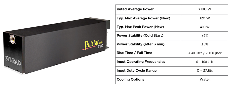
Laser processing of certain materials greatly benefits from pulsed operation of CO2 lasers. Therefore, the design choices towards the RF architecture need to be modified to create a laser that excels at pulsing. Here, the full duty cycle range is sacrificed to generate a RF that can generate a lot higher energy pulses into the laser gas resulting into output pulses that are 2x-4x higher than the average power rating of the laser but simultaneously limiting the duty cycle range to 35%-65% (see Fig. 5). The total amount of energy produced by the pulsed laser is the same as for a comparable CW laser. It is just that its distribution over time is different.
As a result, pulsed lasers are optimal for drilling and perforating applications at high speed, and cutting applications where high peak powers are needed to either pierce hard to process materials such as metals and ceramics or reduce heat affect zones on sensitive materials such as plastic and leather.
In cases where a pulsed laser needs to operate in a more CW like fashion for multi-task applications, a high PWM input frequency can still be used where the commanded pulses are much shorter than the rise-and-fall time of the laser. This will produce optical output that is close to CW with only a slight ripple but it still isn’t as good as using a true CW laser at the same frequencies such as the ti100.
In cases where a pulsed laser needs to operate in a more CW like fashion for multi-task applications, a high PWM input frequency can still be used where the commanded pulses are much shorter than the rise-and-fall time of the laser. This will produce optical output that is close to CW with only a slight ripple but it still isn’t as good as using a true CW laser at the same frequencies such as the ti100.
Fig 5. Popular pulsed laser model from Synrad product brand, p100
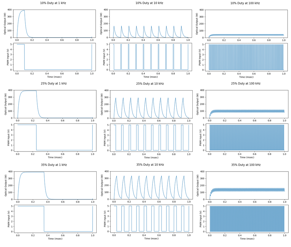
Figure 6 shows the output characteristics of a Synrad Pulstar P100 Laser at nine graphics on duty cycle and frequency settings, similar as Figure 4 shows for a ti100. All axis ranges and settings are directly comparable between Figures 4 and 6 with the exception that low, medium, and high duty cycle settings for a P100 mean 10%, 25% and 35% instead of 30%, 65% and 95%.
Fig 6. Pulsed laser operation – p100
At 1kHz single pulses can be seen for the ti100 and for the P100, while the pulses for the P100 show a much higher output power of 400W and respectively the pulses contain a lot more energy. For medium frequencies the modulation depth of the pulses of a P100 is still at 100% for nearly all accepted duty cycles which allows for great flexibility within this mode. Only at very high frequencies, the individual pulses shrink together allowing for a more CW-like emission output. It should still be noted that the modulation between pulses is still significantly higher than for a CW-laser in this mode and that the average power needs to be selected in a narrow range of duty cycles.
An Application Example That Benefits From A CW Laser
A 0.25 mm thick UV blocking acrylic-based film for a display panel application needed to be scored at a very consistent depth for a fold line later in the process. Ultimately, a very flat smooth optical output was needed from the laser for a consistent process.
First a p100 laser with a 120 µm focused spot size was scanned across the material at 5 m/sec with a duty cycle of 30% at 100 kHz. The maximum frequency of the p100 was used to get as smooth of a score line as possible by blending the optical pulses as close together as possible (See the plots on right side of Figure 6). However, a fair amount of depth of modulation can still be seen, which creates a slight ripple in the width and depth of the score line.
Next a ti100 laser was used with the same setup and focused spot size. However, since it was a CW laser, it was run at a higher duty cycle to get the same average power output with operating parameters of 80% duty cycle at 100 kHz. This resulted in a much smoother score line edge as shown in the comparison Figure 7. For further consistent production, it should be noted that there is the ti100-HS model which delivers even better power stability.
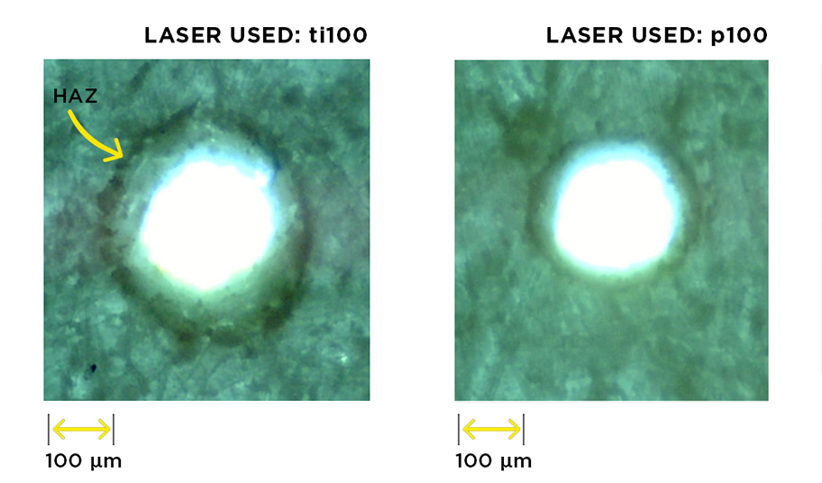
Fig. 8. ti100 (left) vs. p100 (right) perforation performance on paper
結論
Within this whitepaper, we explained how the input PWM signal and its duty cycle and frequency settings interact with pulsed and CW lasers. Depending on the internal laser design, same settings can lead to differing optical output characteristics and thus have large effects on the laser material interaction and thus ultimately lead to differing results with respect to achievable quality and throughput speed. While higher peak power is useful for minimizing HAZ and more optimal drilling and perforating processes, it can be a hindrance for applications that require true CW optical output such as smooth edges on continuous cutting, marking, or scoring applications. Feel free to reach out to Novanta’s 5 Photonics Application Centers across the US, Europe and Asia to learn more about how selecting the right Laser for your individual application can help increase throughput and quality.
Novanta ベネフィッツ
Novanta is uniquely positioned to solve even the most complex challenges for OEMs, system integrators, and end-use customers seeking to advance their manufacturing processes with high precision laser systems. With some of the most well-known brands in the industry and in-country application and service support, Novanta delivers reliable, precise, and durable components and sub-systems.
Our Applications Testing Labs offer application and proof-of-concept testing to OEMs, system integrators, material manufacturers, processors, and end-users of automated machinery. Novanta Application Engineers are laser processing experts, and understand the parameters that will ensure successful, efficient laser processing. Using laser and beam steering equipment from well-known Novanta brands, our Application Engineers will determine the key product parameters and processing know-how to achieve the desired results.