The CO2 laser source can be thought of in a general sense like the engine in a car. You may have a great engine in your vehicle, but if the transmission is poor or the wheels fall off, then you are not going to get very far down the road. This is much the same with laser processing systems: great care must be taken not only in choosing the correct Synrad laser source, but also in delivering that laser beam to the target material in the most efficient beam delivery method possible for the application requirements.
This paper will demonstrate how a different beam delivery method can lead to dramatic differences in cut quality and speed, despite using the same laser source. In this white paper, we will look at two common methods of delivering the beam for cutting applications: a scan head with galvo-mirrors compared to a cut head with a gas jet manifold. Each method has its own advantages and disadvantages depending on the material type and thickness as well as the cut quality and velocity requirements for the particular application. While no solution is perfect, carefully balancing these process needs will lead to the best outcome for the application.
Two Common Beam Delivery Methods
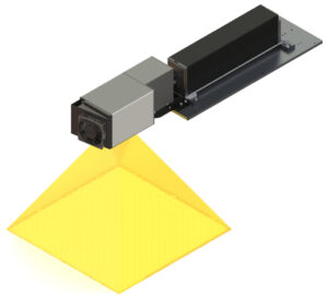
• A scan head uses two galvo-mirrors to steer the laser beam across the material surface in the X and Y directions. This is most often used to mark material, but scan heads are also useful for many cutting applications on materials such as thin plastic films, paper, and cardboard. Surprisingly, some specific plastic types can be cut even when the thicknesses are quite large. Note that directing assist gas into the local cut regions is not possible, but sometimes air may be blown from the side of the scan area to clear debris and cool the material.
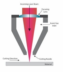
• A cut head houses the focusing lens and gas jet manifold for laser processing while being mounted to an XY-gantry system or fixed-focus system. Although these devices can be used for marking or engraving materials, as the name implies, the primary purpose of a cut head is to provide coaxial air assist during cutting and drilling processes.
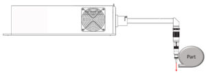
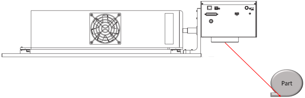
Fig. 1: Example of a scan head setup: the galvo- mirrors provide quick, accurate motion to steer the beam across the material.Fig. 2: Schematic of a cut head: these devices are often mounted to XY gantries or fixed-focus systems to cut or drill materials.
Material Type
Cutting with a CO2 laser involves three very different material interactions depending on the type of material: vaporization, melt shearing, or chemical degradation. For plastics, like acrylic, that absorb the 10.6 μm CO2 wavelength very well, the cut process mainly consists of vaporization. Because the cut process is so efficient, there is little heat input to the surrounding material. For thin materials, this means no assist gas is needed to cool the surrounding material in order to maintain high quality cuts. However, when the plastic type does not absorb the CO2 beam as well, the result is greater heat input and the cut process is mainly melt shearing. In this situation, a focused assist gas is required to eject the molten plastic material and cool the surrounding surfaces to eliminate melt-back and flame-up. An example of this is polyethylene, which does not absorb the CO2 wavelength well, so there is minimal vaporization but plenty of melting. In the most extreme cases, the third mechanism is chemical degradation, where charring due to carbonization is produced and leads to severe discoloring of the cut edge.
Examples of this are thermoset epoxies for FR4 in PCB’s that have cross-linked polymer chains leading to easy charring. Understanding these material interactions will be necessary for choosing the proper beam delivery method.
Advantages of Scan Head Delivery for Fast Cutting of Thin Materials On-the-Fly
Light, galvo-driven scan heads are capable of steering the beam extremely quickly. On the other hand, a cut head is often paired with a bulky gantry system responsible for moving the cut head or in some cases the material. This limits the acceleration and deceleration performance greatly compared to a scan head, especially for small intricate moves.
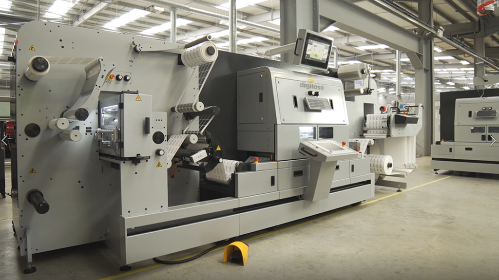
Fig. 3: Example of a roll-to-roll label cutting system. The scan head is located in the central housing (just below the monitor) and is responsible for cutting each label on-the-fly as the material moves beneath.
For these reasons, a galvo scan head is an excellent beam delivery method choice for cutting thin materials very quickly, especially for on-the-fly converting applications like labeling and packaging. A typical converting setup will include some rollers unwinding the web of raw film material with an encoder monitoring velocity in real-time. This information is fed back to the scan head and changes can be made in real-time to the cut vectors to compensate for any changes in velocity, especially during ramp up and ramp down. These web speeds are typically very fast, 50-100 meter/min or more, and the required cut speeds needed to keep up are impossible to do with cut heads on x-y stages.
Advantages of Scan Head Delivery for Cutting Complex Shapes Quickly in Thin Materials
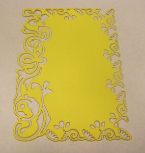
Fig. 4: Laser cutting example
A scan head really shows its speed advantages for complex cut shapes with lots of tight corners. This is where the cut head’s mass decelerating and accelerating around tight corners slows it down. In one lab test example, the project was for cutting card stock into complex flowery patterns around the perimeter of a card measuring 105 mm x 150 mm (4.1” x 5.9”). A cut head on an XY gantry produced cycle- times ranging from 3-5 minutes using a 25 W laser. Because of all the tight corners, the motion system would often have to come to an almost complete stop on some of the smallest flower petal shapes, resulting in longer cycle times regardless of laser power. Next that same 25 W laser was configured with a 2-axis FH Flyer scan head (equipped with a 370 mm focal length lens)—all controlled by Synrad WinMark Pro laser marking software. This configuration with the long focal length lens produced a focused spot size of 540 μm (0.021”) on the card surface. The cut velocity was set to 89 mm/ sec (3.5 ips) and the resulting cycle time was only 39 seconds. The scan head’s galvo- mirrors were able to quickly cut the fine detail of the flower petals resulting in an over 5X throughput increase verses the XY gantry.
The scan head’s ability to quickly maneuver and position the laser beam anywhere in its field of view is an advantage not just in intricate cutting applications, but any time thin materials need to be processed at high speeds. Other examples include selective cutting of label materials or cutting and perforating flexible packaging.
Advantages of Scan Head Delivery for Clearance Issues on Hard- To-Reach Areas (Gate Cutting)
Fig. 5: CO2 laser with laser scan head.
A cut head with a gas jet manifold will often run into clearance issues on parts that are not flat sheet stock. This is a physical constraint caused by the focal point of the laser being located just below the nozzle outlet. The size of the nozzle then dictates how close the laser can cut to tight corners or sharp edges. This often happens when cutting gates off molded plastic, as seen here.
On the other hand, a galvo scan head typically has a large working distance from the beam exit down to the material surface, which allows greater flexibility to get the focused beam in close to the part edge at a specific angle.
The scan head’s large working distance allows it to perform processes in tight or hard to reach locations on parts. This can also allow easier integration with other equipment like part handling or vision inspection cameras. Finally, this setup has a larger depth of focus, meaning the laser will remain in focus across shallow curves or flat sheet distortion.
Fig. 6: CO2 laser and scan head sub-system.
Advantages of Cut Head for Smaller Spot Sizes and Larger Field of View
On the other hand, a cut head can have focusing lens configurations with very short working distances. This allows very small focused spot sizes for fine detail cuts. Having a smaller spot size also gives higher power density, leading to quicker cut speeds in low to moderate throughput processes—where the motion system is not the limiting factor. In addition, the focusing lens does not limit the field of view like a galvo scan head. Rather it is the gantry’s range of motion that determines the field size, so very large pieces can be cut.
Fig. 7: 25 W cut with scan head and 180 μm spot size at 127 mm/sec (5 ips)Fig. 8: 25 W cut with gas jet manifold and 100 μm spot size at 170 mm/sec (6.7 ips)
One example of this decision was an application to cut large sheets of 0.25 mm thick acrylic film in large simple shapes. While fairly good cut quality was obtained with a scan head, the cut speed was almost too slow for the laser power desired (due to the large focused spot decreasing the power density) and the process area visible to the scan head was quite small. This initial test setup consisted of a 25 W laser and a 2-axis FH Flyer head (equipped with a 125 mm focal length lens)—all controlled by Synrad WinMark Pro laser marking software. This lens configuration produced a focused spot size of 180 μm (0.007”) on the plastic surface and provided a process area measuring 85.7 mm x 105.6 mm (3.4” x 4.2”).
Next a cut head setup was tested with a 2.5” FL lens in the gas jet manifold assembly. This shorter focal length reduced the focused spot size to 100 μm. As a result, the cut speed could be increased from 127 mm/sec (5 ips) to 170 mm/sec (6.7 ips) while still only using 25 W of laser power, thus increasing the process margin to a comfortable level. The smaller focused spot sizes possible with cut heads allow for small feature processing and higher power density, leading to faster processing in certain applications. Use with an XY gantry system also increases the processing area to the size of the gantry for large part applications.
Advantages of Cut Head for Thick Material Cutting
For large material thickness, the co-axial assist gas through a cut head becomes critical for most materials cut through melt shearing.
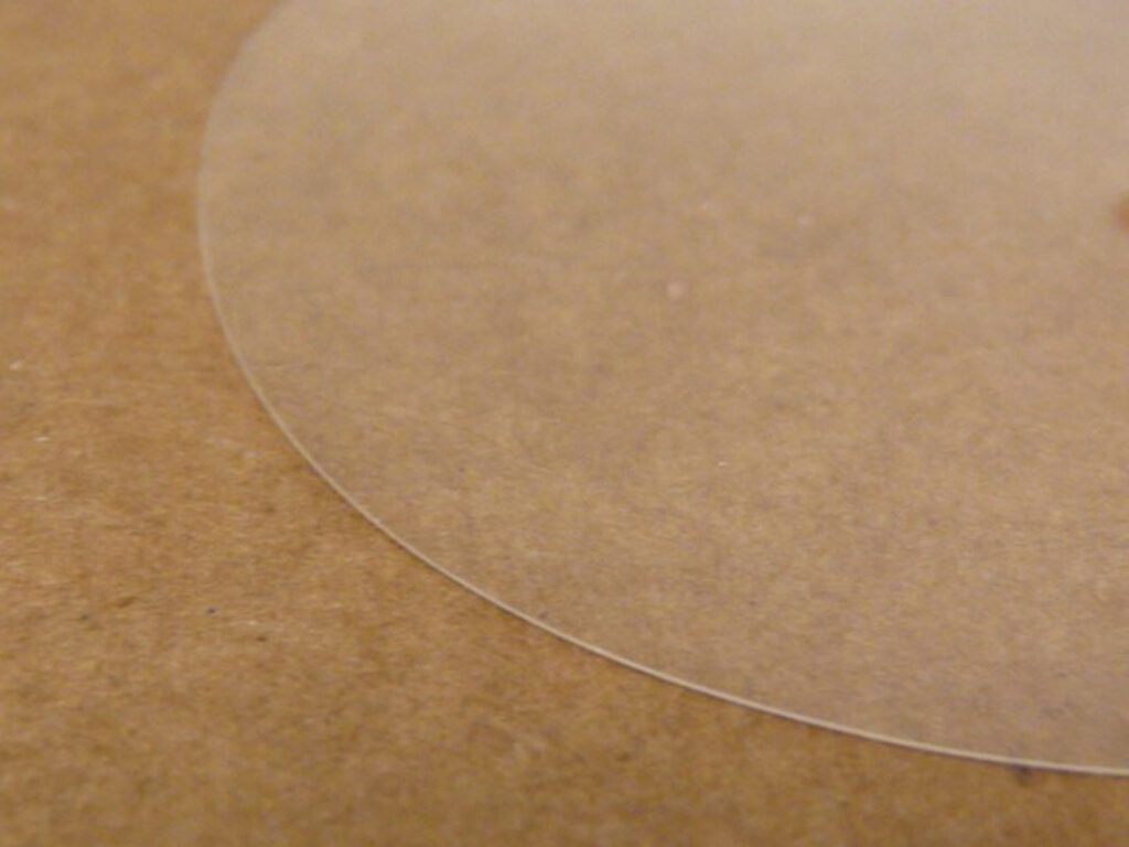
An example of the decision to cut with a scan head or cut head was evident in a project where the requirement was to cut a clear PETG plastic window panel at high speed. The PETG panel was fairly thin, measuring only 1 mm (0.04”) thick, so for speed and ease of integration, the first choice was the Synrad 2-axis FH Flyer scan head. Similar thicknesses of acrylic have been successfully cut with the Flyer (without assist gas); therefore, the test would determine how well PETG’s absorption properties compared to that of acrylic.
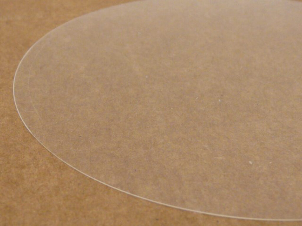
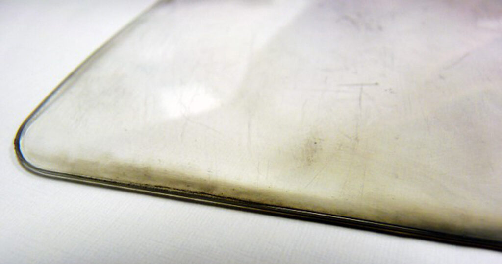
Fig. 9: 1 mm thick PETG cut with a scan head, creating discolored edges.Fig. 10: 1 mm thick PETG cut with XY Gantry and cut head with air assist.
The initial test setup consisted of a 100 W laser and an FH Flyer head (equipped with a 370 mm focal length lens)—all controlled by Synrad WinMark Pro laser marking software. This configuration with the long focal length lens produced a focused spot size of 540 μm (0.021”) on the plastic surface and provided a process area measuring 241 mm x 297 mm (9.5” x 11.7”) which was required to cut an entire panel. The PETG material cut at a speed of 76 millimeters per second (3 in/sec) with this setup, but large flame-ups were seen while cutting and the material edges were charred. Obviously unlike acrylic, the cut mechanism for PETG is melt shearing and chemical degradation, which introduces too much heat into the material.
The second test setup consisted of a 100 W laser in conjunction with the lab’s XY table and a cutting head outfitted with a 2.5” focal length lens that provided a 100 μm (0.004”) focused spot size. The benefit of using the XY table is that maximum part size is dictated by the table’s physical dimensions and not by the field size of the focusing lens as in a marking system. The XY table option allowed us to choose a shorter focal length lens to get a smaller spot size and better power density. Air assist at 40 PSI was directed through the cutting head to eject molten plastic and reduce flame-up of the PETG. Using this setup, the plastic was cut at a speed 165 mm/sec (6.5 ips), resulting in cut edges that are clean and free of discoloration or excessive melting.
The cutting head’s smaller spot size allows much faster cut speed due to higher power density and the edge quality is much better due to the cooling effect of the assist gas.
Advantages for Cut Head to Obtain Vertical Edges
Another advantage of a cut head beam delivery method for thick materials is that the beam is always entering the material surface at a perpendicular angle, resulting in straight profile cuts with no taper. On the other hand, a scan head introduces an angle of incidence, meaning the cut will not have a straight vertical edge unless it is at the center of the field. For thin materials, this is not a problem, but thicker materials will display sloped edges if cut with a scan head.
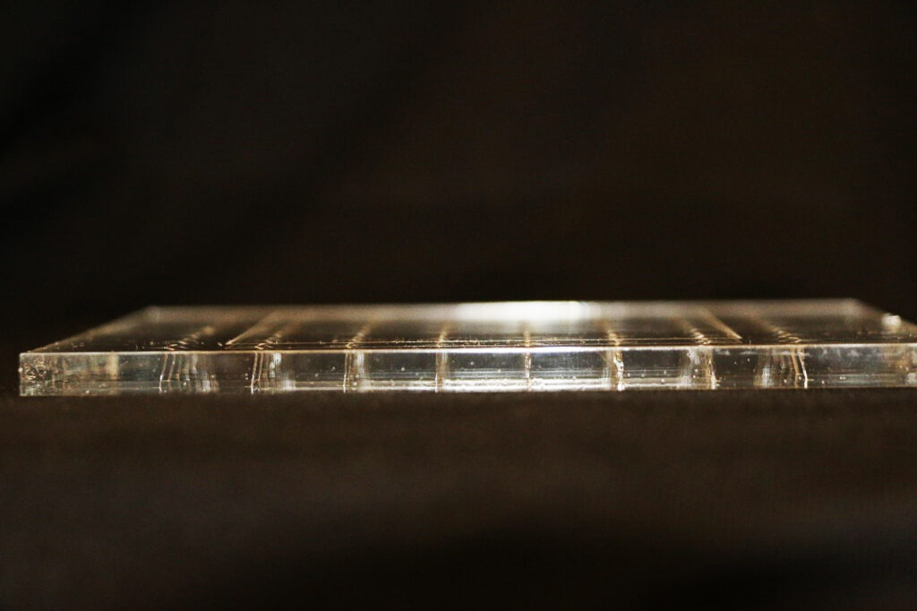
Fig. 11: A side profile of holes drilled through an acrylic sheet with a scan head shows an increasing incident angle away from the center of the field.
Summary
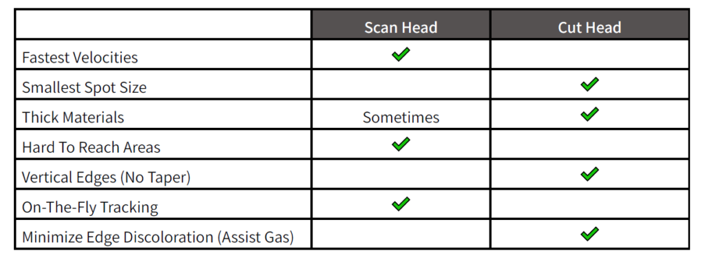
To summarize, in this paper we analyzed two common methods of delivering the laser beam for cutting applications: a scan head vs. a cut head. Each method had its own advantages and disadvantages depending on the material type and application requirements, which are summarized in the table below. While no solution is perfect, careful balancing of these process needs will lead to the best outcome for the application.
Beam Delivery Method Advantages & Disadvantages
ノヴァンタについて
Who we are is inevitably embedded in what we do, our innovations, and the people that make it happen. Our core strength is delivering market-leading solutions for our customers, but also maintaining deep and long-lasting customer relationships. We do this through our global application sales force, and quality-focused manufacturing expertise. It is thanks to what we accomplished in our past and our continuous work towards innovation, that makes us who we are today.
Novanta is a trusted technology partner to medical and industrial OEMs (original equipment manufacturers). Additionally, Novanta holds deep proprietary expertise in photonics, vision and precision motion technologies. We engineer mission-critical core components and subsystems that deliver extreme precision and performance. This enabling our customers to improve productivity, to achieve breakthrough performance and to enhance people’s lives.
Building a high-performing culture enables us to achieve our growth goals. It starts with cohesive teams that engage and align around our vision and strategy. Those who live our values and drive performance through the Novanta Growth System. This is a common set of tools and processes for continuous improvement.
Our highly engineered component and sub-system solutions, and deep expertise in advanced photonics, vision and precision motion make us the global technology partner of choice for medical and advanced industrial OEMs.
Learn more about Novanta by contacting us here.
Interested in a career with Novanta? Check out our job listings here.