デジタル・サーボがシステムをよりスマートに動作させる3つの理由
Manufacturing systems are constantly evolving. It all trickles down to components that can keep up with shifting demands. These components need to be capable of handling higher performance, changing system processes, and increasing technology changes. Laser processing for medical, imaging, marking and manufacturing applications continue to grow exponentially. Indeed, demand has rapidly increased for optimized performance delivered through digital technology. Traditionally, the analog servo driver has been the benchmark for performance, but as technology demand has changed. Indeed, users have started to adopt digital technology to their systems. Digital servos steer laser beams with higher precision, flexibility and finesse than analog servos. Let’s break down all the key benefits of why switching from analog to digital technology helps manufacturing systems operate smarter.Digital Servos: Work Smarter with State Space Technology
One of the biggest benefits of digital servos is State Space technology because it uses real-time system feedback communication, syncing the system and component seamlessly. We bring this feedback into the State Space Model using an Observer. (FIGURE 1). Every time we apply the actual drive voltage to the real galvanometer (also referred to as galvo), we apply a simulated voltage to the model of the galvo to generate its current state. The Observer combines the measured system feedback with calculated feedback, and outputs a correction feedback to the controller.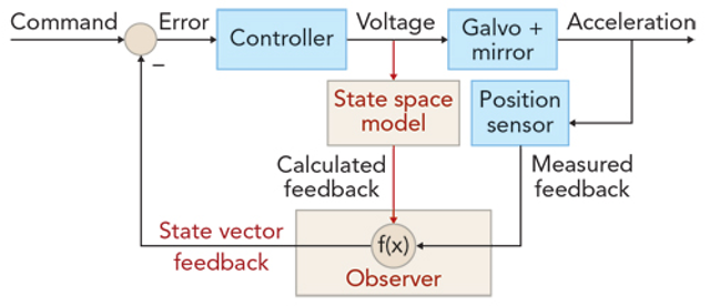
FIGURE 1. Shown is the typical control loop used within an Observer-based digital servo.
Since the State Space Model provides insight to the future state of the system, it allows for predictive positioning control. For example, if the model knows the required acceleration needed to complete a job, it can auto adjust based on its capacity. If the drive capability proves insufficient, operators can modify the command input to stay within the physical limits of the system. This modification allows the servo driver to work intelligently and deliver peak performance throughout the job. In the following sections, we explore how this example of command optimization can improve marking throughput from 30% to 100% over analog servo technology without sacrificing mark quality.Digital Servos: Maintain Quality with Zero Tracking Delay
Velocity-limited commands used in vector patterns are a common pain in traditional marking. Because of large acceleration requirements at the vector end points, the analog servo driver must include filtering to add a delay in the galvo’s response to a given command, limiting the amount of drive voltage required to change speed and direction. This delay is referred to as the system’s tracking delay and is directly related to the system’s step response time and maximum linear speed. Typical galvo systems have tracking delays between 100 and 1000 µsec. The marking job file must add compensation time for these delays to maintain pattern quality, which limits throughput.Reducing Delay Without Giving Up Stability
The digital servo reduces this tracking delay by 50–100% without giving up stability. With knowledge of the galvo and mirror dynamics accurately captured in its model, the control algorithm within the digital servo optimizes the input command profile to limit the acceleration to a value that will keep the servo within drive voltage limits. As a result, we can greatly reduce the tracking delay and deliver increased throughput by removing the additional filtering. In some cases, the digital servo control algorithm can eliminate the tracking error completely. For example, Cambridge Technology’s DC3000 Plus digital servo driver introduces a small delay in the command stream. It uses this delay to analyze the command stream and smooth areas of high acceleration. It then dynamically adapts the bandwidth, when necessary, to apply all of the available drive voltage to lock onto the post-processed command, eliminating the tracking delays (FIGURE 2).
FIGURE 2. Tracking delays introduced by typical analog servos (a) are eliminated by the digital DC3000 Plus servo (b).
Faster Speeds
We can achieve up to 2X faster speeds for the smallest features in marking, micromachining, and trepanning by using zero-tracking-delay algorithms, which limit micro-precision features in the pattern only by the drive voltage instead of the servo bandwidth. Applications like converting and additive manufacturing also benefit by the fact that consistent laser energy density is applied at corners and other precision features in the pattern, enabling crisp pattern quality. Take a look at the example below (FIGURE 3) to see how reduced tracking delays are highlighted by comparing the character quality produced by laser marking using an analog servo with that of the DC3000 Plus digital servo driver running the same 6220H galvo and 10 mm mirror configuration at equal mark/jump speeds and delay settings.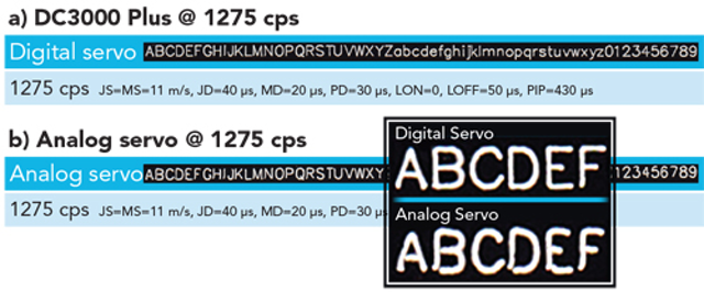
FIGURE 3. Characters marked by a laser on marking paper have significantly higher quality when using a digital servo (a) compared to an analog servo (b).
The relatively small delay settings have been optimized for the digital servo driver and achieve marking speeds of 1275 CPS. Increasing the delay settings by nearly 3X would be necessary to obtain similar character quality using the analog servo driver, and this would result in marking speeds of 900 CPS. This means that the optimized command from the digital servo still maintains all the critical features of the original pattern, so the mark quality remains high while increasing throughput by 40%.