Laser Remote Cutting of Anode Battery Foil: A Comparison of Different Laser Setups
Authors: Eugen Schäfer, Malte Hemmerich
要約
This paper explores remote laser cutting techniques for anode electrode materials in battery cells for e-mobility usage, assessing high brilliance laser performance in different operational modes and setups.In the rapidly evolving landscape of battery technology for electric vehicles, the method of cutting electrode materials plays a critical role in manufacturing efficiency. This paper offers an analysis of remote laser cutting using industrially available high brilliance lasers in continuous wave and pulse mode operation (ns, ps), comparing their dynamic performance and cutting quality to illuminate their potential in optimizing battery manufacturing processes.Microscopic analyses of the beam entrance and exit sides as well as laser scanning microscope measurements provide a comprehensive assessment of the cutting quality and precision. The paper outlines experiments and findings while offering insights into the future possibilities for enhancing electrode manufacturing techniques.
Introduction
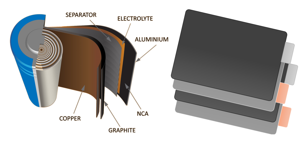
The increasing focus on E-mobility has positioned it as a central theme within the automotive industry, emphasizing vehicles powered by electricity without actively emitting pollutants.This shift has led all global automotive players to increasingly produce electric-only and hybrid cars. Today both typesrely mainly on lithium-ion batteries, increasing the demand for high-performance cells. Battery packaging comes in various forms - prismatic, cylindrical, and pouch - all sharing a common architecture including multiple layers of anode-separator-cathode foils (seeFigure 1).Figure 1: Common lithium-ion battery structures; left cylindrical – right pouch
The tailoring of electrode foils traditionally relies on mechanical cutting processes such as punching and blade cutting, which exhibits notable drawbacks, such as tool wear, metal layer smearing, and limited contour adaptability. Changing the shape of the electrode requires redesigning of the cutting tools, which increases costs. In contrast, laser remote cutting has emerged as a proven, efficient, and reliable manufacturing method, already used across industries. The distinct advantages of laser remote cutting, including a non-contact process, and high processing speed outweigh those of mechanical cutting. Notably, the simplicity and cost-effectiveness of laser cutting geometry redesign and its excellent suitability for in-line roll-to-roll processes further underscores its superiority over mechanical processes.
While both coated copper anode and coated aluminum cathode foils are integral to battery manufacturing, this paper's focus primarily centers on the challenges and advancements in cutting coated copper anode materials. The comprehensive scope and intricate parameters involved, coupled with the need for detailed microscopic analysis, necessitated this strategic focus. Nevertheless, it is imperative to acknowledge the equal importance of enhancing cathode cutting methods. Tests on a similar scale to the anode processing described here have also been carried out in our laboratories for cathode processing and can be discussed with interested partners on request.
Overall, the remote laser cutting of coated foils plays a fundamental role in battery manufacturing, paving the way for enhanced precision, reduced manufacturing costs, and improved overall efficiency in the production of lithium-ion batteries for electric vehicles.
Process Requirements
Cutting Strategy
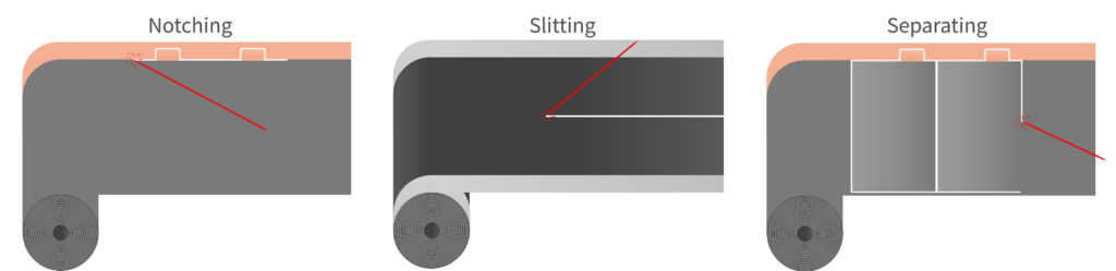
The machine design and electrode manufacturing method as well as the battery cell geometry define the cutting strategy and thus are major limiting factors for the achievable cutting speed. In general, tailoring of any battery foil can be divided into different types of cutting processes; notching, slitting, and separating (see Figure 2). Within this paper we focus on the notching process as it allows us to both look at bare metallic surfaces and the full coated area of the film. Additionally, this process usually requires the highest roll-to-roll machine speeds and thus the most efficient on-the-fly process.
Figure 2: Cutting speed is determined by individual cutting strategy
Material Composition and Thickness
Electrodes are multi-material systems consisting of a base material (current collector) and an active top and bottom coating. The thickness of the base material and coating varies from manufacturer to manufacturer. Anodes have a copper base material with a thickness between 5 and 15 µm, coated on both sides with active material (graphite). The total thickness of an anode to be cut varies between 100 and 150 µm.
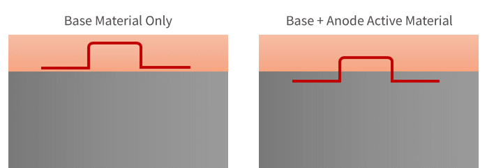
Figure 3: Different use cases for notching
Depending on the use case (see Figure 3), the material itself and thickness to cut result in different parameters. Cutting uncoated copper as thin as 10 µm can be performed with a 1kW single-mode CW (Continuous Wave) fiber laser at speeds up to 20 m/s with excellent quality. However, when it comes to cutting through all layers, the overall thickness and various laser-material interactions lead to a significant drop in cutting speed and cut quality. This paper focuses on the more sophisticated process of cutting through both areas as shown on the right side in Figure 3.
Cutting Quality and Speed
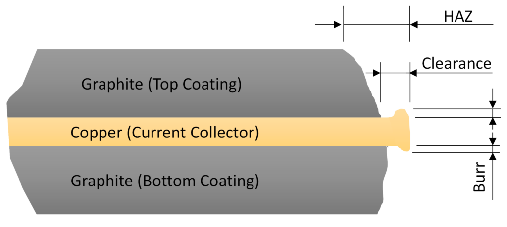
Electrodes for automotive applications require high cut quality, which is defined by excellent geometric accuracy, minimal burr and clearance width, low spatter and debris distribution, and a small heat-affected zone (HAZ). The presence of debris and spatter is not only a concern with respect to battery efficiency but could in the worst case, lead to separator film punctation and ultimately to catastrophic destruction of the battery cell. The cut quality criteria “Heat Affected Zone (HAZ)”, “Clearance” and “Burr” are illustrated in Figure 4.
Figure 4: Schematic cross section view of battery foil after laser cutting
In addition to the required cut quality, an average cutting speed of more than 1 m/s is typically required to compete with die cutting processes. Cutting speed and quality can be optimized separately for coated and uncoated areas. However, cutting through both coated and uncoated areas (called tab cutting) requires a compromise between speed and quality.
Laser Remote Cutting Process
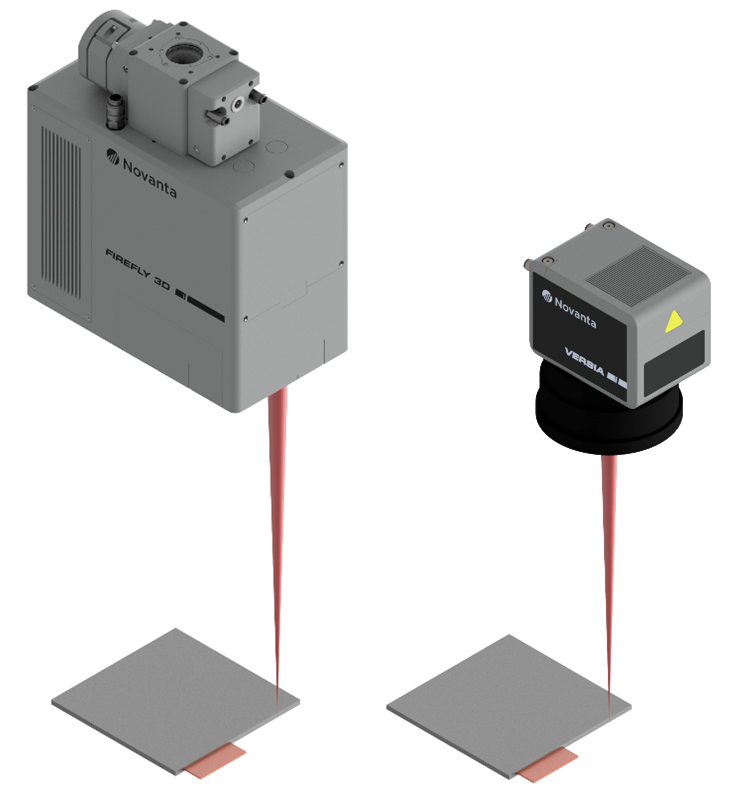
While the cut quality towards HAZ, clearance and burr can often be optimized using assist gas driven cutting processes such as fusion and oxidization cutting, these techniques require the use of static optic cutting heads. Such cutting heads operate close to the target and are limited in speed by the moment of inertia, making this technique unsuitable for notch cutting of electrodes. The high dynamics involved in this roll-to-roll process necessitates the use of galvanometer-based scanning heads (see Figure 5) within a vaporization driven remote cutting process. While both 2D and 3D scanning systems are industrially considered within this segment, the careful selection of the correct galvos, galvo tune, servos control method and optical components are crucial for achieving success. The choices made have imperative effect on the achievable dynamics, maximum velocity, positioning accuracy, repeatability, thermal and long-term drift, optical caustic parameters, all of which directly effect and determine the achievable cutting speed and quality. For this paper, a 2-axis digital scanning head with a 21mm aperture was selected in combination with four different F-Theta lenses.
Figure 5: FIREFLY3D fully digital 3-axis scanning head (left) and VERSIA hybrid 2-axis scanning head (right) in remote laser cutting configuration
Experiments
Experimental Setups and Procedure
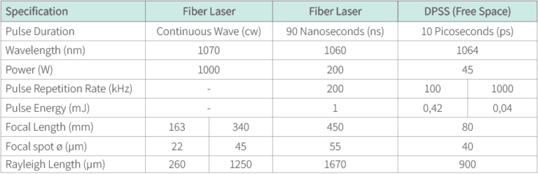
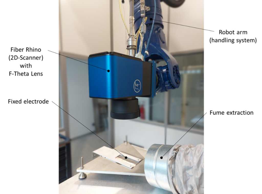
Three different types of lasers were used to cut the anode material: A continuous wave (cw) fiber laser, and a short pulse (ns) fiber laser and a free space ultra short pulse (ps) laser. The cw fiber laser was used with two different f-Theta lenses, with 163 mm (shown in 6) and 340 mm focal lengths to compare the influence of the focal spot size. The effect of the pulse energy was investigated using the ps-laser, by applying pulses at 100kHz and 1000kHz, respectively. Characteristics of the individual experimental setups are given in Figure 6.
Figure 6: Laser Setup characteristics
All experiments were performed under the same conditions. The laser source was set to maximum power and individual cuts of 30 mm length were performed on the electrode foils using a galvo scanner. The cutting speed was steadily increased with each cut line. Only cuts that passed through the entire electrode structure, top coating, base material and bottom coating, were evaluated. The cutting tests were carried out in a single pass to facilitate the On-The-Fly process.
Figure 7: 1kW SM fiber Laser with 21mm digital scan head and 163mm F-Theta Lens
Results
Uncoated Base Material
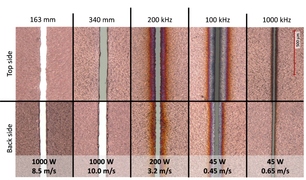
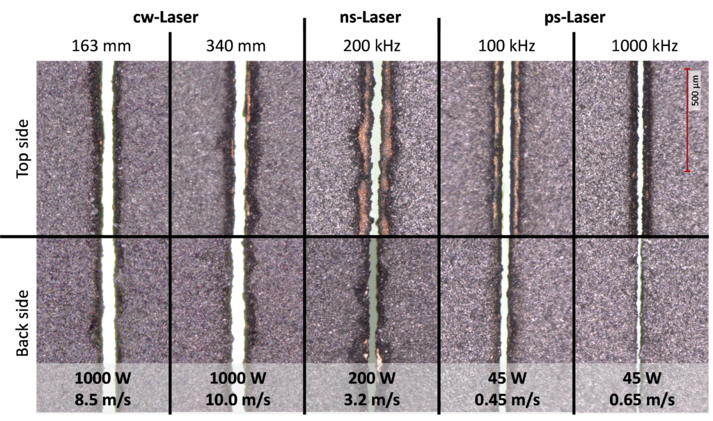
The top and back side of the uncoated copper current collector after laser cutting are shown in Figure 8. The quality of the cut was inspected visually by using a digital microscope (Keyence VHX-2000). All images were taken at the same magnification, the scale is shown in the upper right corner. Results for the coated foil areas are shown in Figure 10. The first row (top side) shows the laser entrance side, and the second row (back side) shows the laser exit side. The columns show the setup and laser power used and the maximum cutting speed achieved.
Figure 8: Cutting results of anode, base material (Cu) only, with a thickness of 10 µm
The highest cutting speeds are achieved with the cw-laser. However, the cw-laser results also show melted cutting edges that become visible as a burr. High cutting speeds of several meters per second are possible due to the available high average power of the cw-laser. The cw-laser cutting results show no discoloration at all.
The pulsed ns-lasers show less melting but a more frayed cut edge and discoloration to the top and back sides.
In terms of quality, the best but slowest results on uncoated copper foil (anode current collector) were obtained with the pulsed ps-laser. The low cutting performance being due to the low average power available. Increasing the pulse repetition rate from 100kHz to 1000kHz slightly increases the cutting speed whilst significantly reducing the discoloration on both sides. The high pulse overlap when using the high pulse repetition rate of 1000kHz at the low cutting speed of 0.65 m/s makes the ps-laser process similar to the cutting behavior of the cw laser.
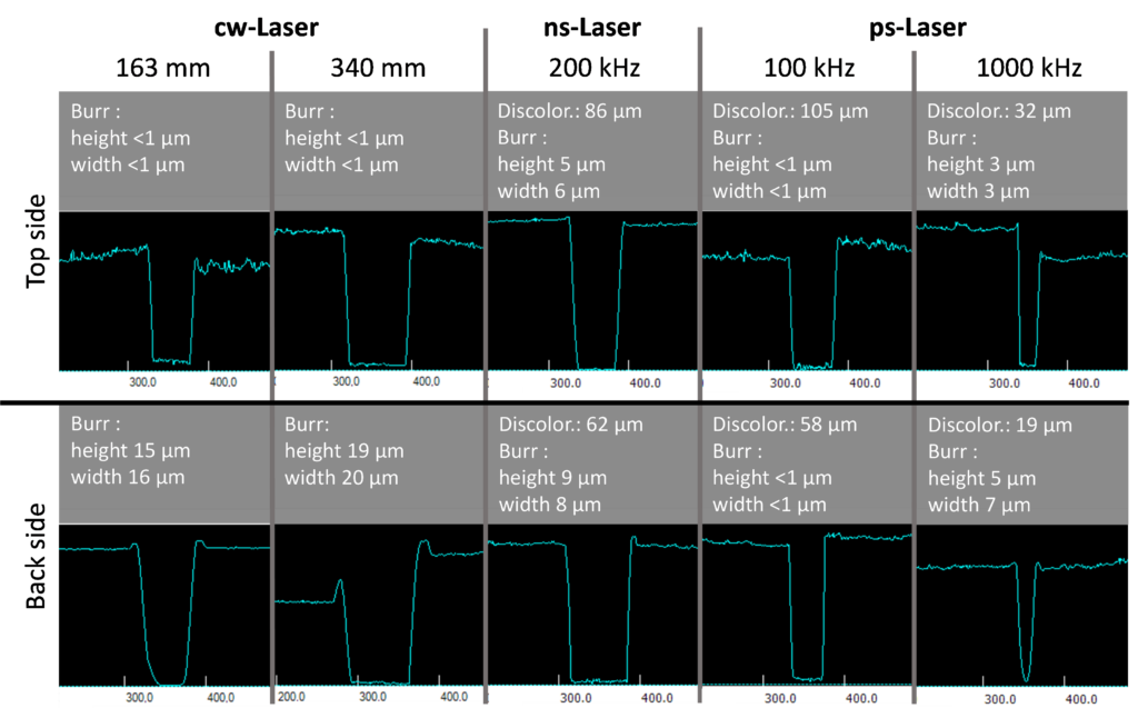
A laser scanning microscope (Keyence VK-X210) was used for the profile measurements. The measurement results are shown in Figure 9 for the uncoated electrode and in Figure 11 for the coated electrode.
Figure 9: Profile measurement of anode, base material (Cu) only after cutting
The cw-laser produces a burr of up to 19µm on the back side - almost twice the thickness of the copper base material (10µm). The 163 mm f-theta lens shows slightly less burr than the 340 mm focal length lens. The top side appears to be burr free.
The ns-laser setup produces a small burr on the top and back side, both are below the thickness of the copper base material.
The lowest burr results are obtained with the ps-laser at 100kHz pulse repetition rate. Increasing the pulse repetition rate to 1000kHz produces small burrs of 3µm on the top and 5µm on the back side.
With a high brilliance cw laser of 1000W average power, the anode electrode can be cut at a speed of 8.5 m/s with a 163 mm f-theta lens. Using a 340 mm f-theta lens, the cutting speed increases to 10 m/s. This may seem surprising at first, since a 163 mm lens produces a focal spot that is half the diameter of a 340 mm lens, and thus produces 4 times the intensity (W/mm²) on the target. This can be explained by the Rayleigh length of both setups. The 163 mm lens produces a small focal diameter of 22µm, but at the same time, the Rayleigh length of the setup is limited to 260µm. For the given optical performance, the 163 mm setup is extremely sensitive to changes in focus position, such as setup tolerances and misalignment or wrinkled foils. Comparing the 163 mm and 340 mm f-theta lenses, the longer focal length 340 mm lens produces a spot diameter of 45µm, which is twice the size of the 163 mm lens. However, the 340 mm lens provides a Rayleigh length of 1250 µm, that is almost 5 times more than the 163 mm lens. The longer Rayleigh length ensures that the process is stable even at high speeds, which is beneficial for industrial manufacturing.
Due to the limited average laser power, the maximum possible cutting speed of the pulsed lasers is reduced accordingly. In the case of ns-laser, the cutting speed is limited to 3.2 m/s due to the 200W average laser power. And for the ps-laser, with an average power of 45W, the cutting speed drops to 0.45 m/s at 100kHz and 0.65 m/s at 1000kHz.
Coated Base Material
Figure 10: Cutting results of Anode, base and active material with a thickness of 130 µm.
Conversely to the uncoated copper substrate, where discoloration varied according to the laser used, the graphite coated substrate exhibited HAZ discoloration for all laser types.
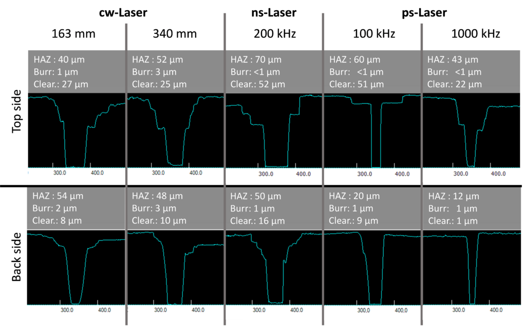
Profile measurements with the laser scanning microscope offer a clear view of the cutting quality.
Figure 11: Profile measurement of anode, coated copper after cutting
The cw-laser and the ps-laser at high pulse repetition rate generate the smallest clearance on the top side. Clearence is also referred to as foil exposure. The clearance produced by the ns-laser is twice that of the cw-laser. The same clearance as the ns-laser is produced when the ps-laser is operated at 100kHz. The smallest clearance on the back side of the electrode is produced by the ps-laser running at 1000kHz.
Conclusion and Summary
The performance of lithium-ion batteries is affected by the electrode cut surface's quality, which is related to the battery cell's stability over time. Quality and speed have always been adversaries. Increasing speed without sacrificing quality is not an easy task.
Of course, the most important evaluation parameter is the quality of the cut, which ideally should be burr-free and without spatter and melt deposits. Laser remote cutting has shown outstanding performance in terms of cutting speed, short processing times and flexible adaptation to desired geometries in a non-contact process. However, due to the physical principle of laser remote cutting, there are challenges with cut quality in terms of clearance and burr. The presented results provide a clear overview of the cutting speeds achievable with different types of lasers.
Three different types of lasers were used in the cutting experiments. Continuous wave (cw) fiber laser, short pulse (ns) fiber laser and ultra short pulse (ps) free space laser.
Highest cutting speeds up to 10 m/s were achieved with a cw-laser with a long focal length lens (340 mm). In contrast, the shorter focal length lens (163mm) cuts at a maximum speed of 8.5 m/s at the same laser power level. The higher cutting speed is possible because of the longer Rayleigh length of the 340 mm f-theta lens which makes the cutting process more stable by covering larger tolerances.
The anode electrodes can be cut at a speed of up to 3.2 m/s with the pulsed ns-laser. Compared with the cw-laser it seems quite slow, but the average power of the used ns-laser was 200W, which is 5x lower than the used cw-laser. By upscaling, the pulsed ns-laser process to industrially available high-power systems with an average power of 1000W, cutting speeds of up to 16m/s, with the quality shown, should be possible if the beam characteristics of both lasers are comparable.
The highest processing quality was achieved with the ps-lasers. The ps-laser used for the tests has an average power of 45W, which reduces the maximum possible cutting speed down to 0.65 m/s. Industrially available ps-laser with 200W average power should be able to achieve cuttings speeds up to 2.8 m/s. The upscaled cutting speed of the ps-laser is still 3.5 times slower than the cw-laser and 5 times slower than the upscaled ns-laser cutting process.
Figure 12: Qualitative ranking of the tested lasers for anode cutting
As always, selecting the right laser depends on the goals of the process and the trade-off of investment cost vs cutting quality vs speed. High-quality cuts with the ps-lasers are slow and can only be used at web speeds of about 50 to 60 m/min, depending on the tab geometry. In addition, the investment cost for the ps-laser is high. CW (Continuous Wave) fiber lasers offer high cutting speed with good cut quality and low investment cost. Pulsed high power ns fiber laser would achieve the highest cutting speed with moderate cutting quality and moderate investment cost. To improve the cutting quality, different cutting strategies such as multi-pass cutting with high performance galvanometer-based systems could be investigated.